Intro to Lab Notes
Lab Notes
Keeping lab notes is an essential aspect of engineering design. These notes can be critical to protecting your IP and proving timelines. Even if you are not developing IP, good lab notes are still useful. Being able to review your design decisions and the problems you encountered, as well as their solutions, can often save you considerable time as the project evolves or is shelved and revisited at a later time.
- Allyson Giannikouris
I should capture:
- Which group members were involved
- Implementation decisions and details such as pin numbers, peripheral wiring, important function names and locations
- Brief summaries of any group discussions and resulting decisions
- Descriptions/details of the procedures you are following, data you collect and analysis of that data
- Notes on any problems you faced and how you solved them
- Address any specific requirements for the objective you are working on
- Log time on your timesheet (see provided template)
Lab Session 1
Git link: https://git.uwaterloo.ca/d35huynh/w23_two_axis_project
Group members involved: Dan, Chelsea, Owen
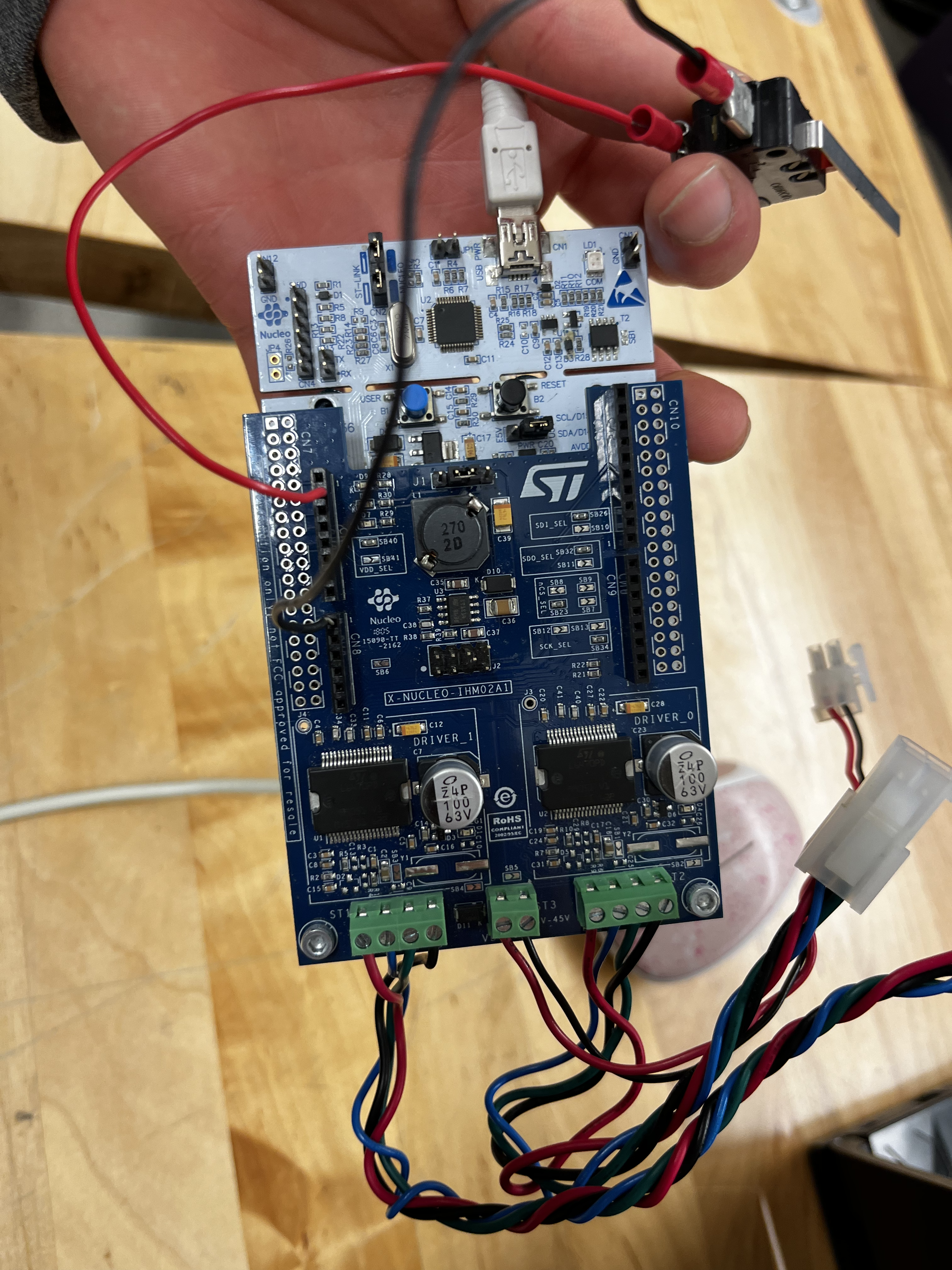
GPIOB (PB0 and PB4) were used to interface with the provided switch, and LED respectively.
3.3V VDD was used to power each peripheral.
The LED was wired in series with a resistor to reduce its input voltage.
Bumps in the road
Originally, GPIOA (PA0 and PA1) were used for interfacing, however, some unknown error after connecting the LED to PA1 caused OpenOCD to fail during initialization causing the board to continuously fail.
A new board was received from the teaching team with the new GPIOB pinouts.
The GPIOB clock was enabled using:
__HAL_RCC_GPIOB_CLK_ENABLE
and the following structs were initialized to read/write to the switch, and LED respectively.
// For the Switch
GPIO_InitTypeDef GPIO_InitStruct;

GPIO_InitStruct.Pin = GPIO_PIN_0;

GPIO_InitStruct.Mode = GPIO_MODE_INPUT;

GPIO_InitStruct.Pull = GPIO_PULLDOWN;

GPIO_InitStruct.Speed = GPIO_SPEED_FAST;

HAL_GPIO_Init(GPIOB, &GPIO_InitStruct);

// For the LED
GPIO_InitTypeDef GPIO_InitStruct_2;

GPIO_InitStruct_2.Pin = GPIO_PIN_4;

GPIO_InitStruct_2.Mode = GPIO_MODE_OUTPUT_PP;

GPIO_InitStruct_2.Pull = GPIO_PULLDOWN;

GPIO_InitStruct_2.Speed = GPIO_SPEED_FAST;

HAL_GPIO_Init(GPIOB, &GPIO_InitStruct_2);
The following line was commented out to avoid errors:
// This is probably only needed for demoing the motors
USART_CheckAppCmd();
A value from PB0 was stored in a buffer and printed to a serial monitor
uint32_t val = HAL_GPIO_ReadPin(GPIOB, GPIO_PIN_0);

char buffer[12];

sprintf(buffer, "%u\n", val);
USART_Transmit(&huart2, buffer);
A value was written to PB4 from the value read from PB0:
HAL_GPIO_WritePin(GPIOB, GPIO_PIN_4, val);
Lack of time
Due to an early board failure, not enough time remained in the lab to finish section 3.4 (the motor demo). However, an understanding of interfacing with GPIO was established for the next lab section.
Furthermore, the code provided for the motor demo was provided, with definitions needing to be commented out / uncommented to switch between a sole motor, and dual motors.
Results
Success
- We were successfully able to read the current state of PB0 (the switch) when opening and closing the switch.
- We were successfully able to write to PB4 (turn the LED on/off) when opening and closing the switch.
Further Notes
After finishing section 3.2 and understanding GPIO interfacing, the remainder of the lab was much easier.
Example Switch Wiring
Lab Session 2
Group members involved: Dan, Owen
Preparation
Before starting the lab, an attempt was made at writing the two methods of synchronization. I had thought I wrote the correct code the first time but in hindsight, I should have made more of an effort to test my code (which could be done by using a switch to simulate a rising clock edge).
4.1
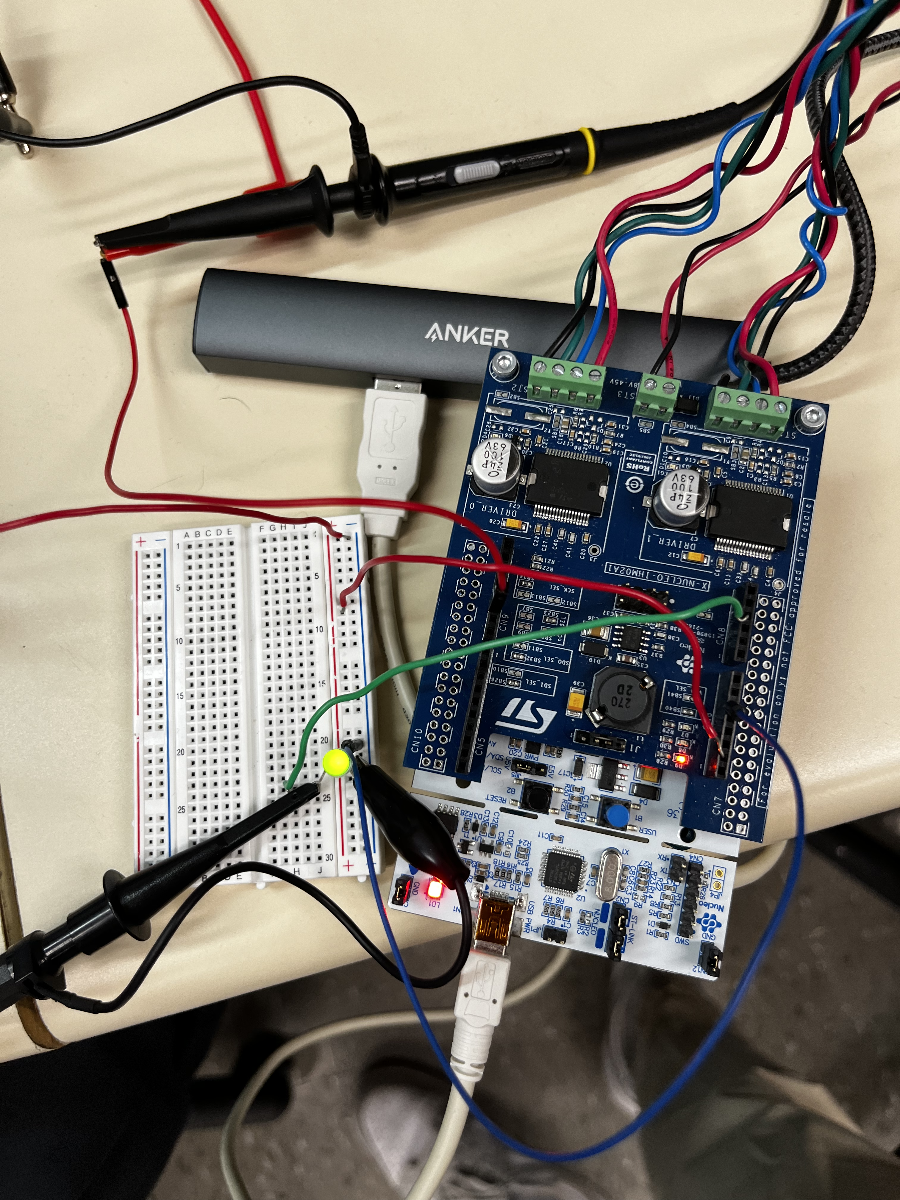
Using the oscilloscope, the signal generator, and the circuit in the lab manual, a circuit was made that generated a waveform, and our systems response to that waveform. We monitored our response by connecting the oscilloscope across the LED.
Using PB4 as the input pin on our chip, and PB8 as the output pin for the LED and oscilloscope, we compiled and flashed our board with our software expecting to see the LED turn on which did not work as expected on attempt #1. After fixing syntax errors and implementing true tight polling, the LED turned on as expected. We could verify that the LED was turning on and off by lowering the frequency of the signal generator and seeing the LED flash which we can’t observe at high frequencies.
void tight_polling(void) {

while (HAL_GPIO_ReadPin(GPIOB, GPIO_PIN_4) == GPIO_PIN_RESET) {}

HAL_GPIO_WritePin(GPIOB, GPIO_PIN_8, GPIO_PIN_SET);

while (HAL_GPIO_ReadPin(GPIOB, GPIO_PIN_4) == GPIO_PIN_SET) {}

HAL_GPIO_WritePin(GPIOB, GPIO_PIN_8, GPIO_PIN_RESET);
}
Prints in polling
Our first attempt at tight polling had a print statement in our loop which we used to verify that we were reading a rising edge which significantly slowed down our system
After establishing that the LED was operating correctly, we essentially just increased our operating frequency by a magnitudes of 10 until the signal began to deteriorate.
Testing Quantitatively
First and foremost, the falling edge of a signal should never occur after the rising edge of a signal, that would mean we skipped a rising edge which would fail hard real-time constraints.
To test quantitatively, we decided that we should use that fact as a hard cutoff and add a safety factor.
We decided on a safety factor of one clock period * 5 as the boundary a falling edge must occur before when considering the signal reliable
4.2
Our circuit was the same as it was in 4.1, and the challenge was essentially the same, except we are implementing an interrupt based synchronization technique.
Bad Code
Once again, our initial code wasn’t working as expected due to syntax errors and probably bad form…
We initially implemented our interrupts using the general IRQ handler but instead used a more straightforward approach to interrupt handling which was accomplished by clearing a flag on the pending register when it was set before turning on the LED.
Huh
After implementing the new interrupt handler, our interrupt-based synchronization method was still not working which ended up being because PB4 didn’t work in this case as our input pin???
We switched our input and output pins (PB4 and PB8) and our interrupt synchronization worked successfully.
Using a similar approach to the method described in 4.1 to find maximum response frequency, our maximum frequency using interrupt-based synchronization was higher than tight-polling which was contrasting to the information I remember hearing in lectures…
Using IRQ Synchronization
void init_GPIO_interrupts(void) {

GPIO_InitTypeDef GPIO_InitStruct;

GPIO_InitStruct.Pin = GPIO_PIN_4;

GPIO_InitStruct.Mode = GPIO_MODE_IT_RISING_FALLING;

GPIO_InitStruct.Pull = GPIO_PULLDOWN;

GPIO_InitStruct.Speed = GPIO_SPEED_FAST;

HAL_GPIO_Init(GPIOB, &GPIO_InitStruct);


HAL_NVIC_SetPriority(EXTI4_IRQn, 1, 1);

HAL_NVIC_EnableIRQ(EXTI4_IRQn);

}
void EXTI4_IRQHandler(void) {
if (__HAL_GPIO_EXTI_GET_IT(GPIO_PIN_4) != GPIO_PIN_RESET)
{
__HAL_GPIO_EXTI_CLEAR_IT(GPIO_PIN_4);
}
HAL_GPIO_TogglePin(GPIOB, GPIO_PIN_0);
}Why use tight-polling?
Since we found interrupt-baed synchronization to be faster, why would we want to ever use tight-polling in this case?
To ensure that our results were consistent, we reverted our software back to tight-polling which was not working as intended at first due to a misplaced (.
Our results ended up being consistent throughout.
The word document contains more details in terms of reflection
Sample Circuit
Lab 3
Pre-lab
Group Members Involved: Dan (design, programming and debugging), Owen (design)
Before the lab, we want to gain familiarity with the motor controller example just by reading through it.
Current Solution Thought Process for Objective D1
The MicrosteppingMotor_Example_01 should be our interface for the motor? We just need to figure out how to send commands to and from the motor outside of the serial.
Solution Flow
- Figure out what pins the X and Y motors required for interfacing
- Create interrupts in the same way that we did in Lab 2 for those pins
- Within those interrupts we need to send a command that reverses the direction of that given motor using the MicrosteppingMotor_Example
- To do so, I have a variable that is the current motor direction which gets flipped by the interrupt
- The MicrosteppingMotor_Example’s StepperMotorBoardHandle→Command→Move API is used to actually set the direction of the motor
Hoping
Theoretically, when the limit switches are actuated, the direction of the motors should reverse.
Finalized Pre-lab code
Interrupts
I ended up using arbitrary GPIO pins for preliminary testing and we will figure out the interfacing during the lab itself when we get hands on the motors and limit switches.
I used PB3 and PB4 as the two “limit switches” and developed two interrupts corresponding to the x and y axis that reversed their respective motor directions according to which interrupt fires.
void init_GPIO_interrupts(void) {

GPIO_InitTypeDef GPIO_InitStruct1;

GPIO_InitStruct1.Pin = GPIO_PIN_4;

GPIO_InitStruct1.Mode = GPIO_MODE_IT_RISING;

GPIO_InitStruct1.Pull = GPIO_PULLDOWN;

GPIO_InitStruct1.Speed = GPIO_SPEED_FAST;

HAL_GPIO_Init(GPIOB, &GPIO_InitStruct1);


HAL_NVIC_SetPriority(EXTI4_IRQn, 1, 1);

HAL_NVIC_EnableIRQ(EXTI4_IRQn);


GPIO_InitTypeDef GPIO_InitStruct2;

GPIO_InitStruct2.Pin = GPIO_PIN_3;

GPIO_InitStruct2.Mode = GPIO_MODE_IT_RISING;

GPIO_InitStruct2.Pull = GPIO_PULLDOWN;

GPIO_InitStruct2.Speed = GPIO_SPEED_FAST;

HAL_GPIO_Init(GPIOB, &GPIO_InitStruct2);


HAL_NVIC_SetPriority(EXTI3_IRQn, 2, 2);

HAL_NVIC_EnableIRQ(EXTI3_IRQn);

}
void EXTI4_IRQHandler(void) {
// !!--CHANGE PINOUT FOR X LIMIT SWITCH SPECIFICS--!!
if (__HAL_GPIO_EXTI_GET_IT(GPIO_PIN_4) != GPIO_PIN_RESET) {
uint32_t current_time = HAL_GetTick();
if ((current_time - last_debounce_time) > DELAY) {
reverse_x_motor_direction();
last_debounce_time = current_time;
}
__HAL_GPIO_EXTI_CLEAR_IT(GPIO_PIN_4);
}
}
void EXTI3_IRQHandler(void) {
// !!--CHANGE PINOUT FOR Y LIMIT SWITCH SPECIFICS--!!
if (__HAL_GPIO_EXTI_GET_IT(GPIO_PIN_3) != GPIO_PIN_RESET) {
uint32_t current_time = HAL_GetTick();
if ((current_time - last_debounce_time) > DELAY) {
reverse_y_motor_direction();
last_debounce_time = current_time;
}
__HAL_GPIO_EXTI_CLEAR_IT(GPIO_PIN_3);
}
}Debouncing
During testing, I noticed that on a single switch actuation, the interrupt was firing multiple times, so I added debouncing to resolve this issue
Reversing Motor Direction
I wrote the following functions to reverse motor direction whilst also printing to the serial monitor for testing
void reverse_x_motor_direction(void){

x_direction = (x_direction == L6470_DIR_FWD_ID) ? L6470_DIR_REV_ID : L6470_DIR_FWD_ID;

if (x_direction == L6470_DIR_FWD_ID) {

USART_Transmit(&huart2, "X FORWARD\n\r");

} else {

USART_Transmit(&huart2, "X REVERSE\n\r");

}

}

void reverse_y_motor_direction(void){

y_direction = (y_direction == L6470_DIR_FWD_ID) ? L6470_DIR_REV_ID : L6470_DIR_FWD_ID;

if (y_direction == L6470_DIR_FWD_ID) {

USART_Transmit(&huart2, "Y FORWARD\n\r");

} else {

USART_Transmit(&huart2, "Y REVERSE\n\r");

}

}
Motor Control
Using MicrosteppingMotor_Example_01 as an example I wrote move_axis to actually interact with a motor given a board and device which is the motor itself
void move_axis(uint8_t board, uint8_t device) {

StepperMotorBoardHandle_t *StepperMotorBoardHandle;

MotorParameterData_t *MotorParameterDataGlobal, *MotorParameterDataSingle;

uint32_t Step;

uint32_t Speed;

uint8_t MovementPerRevolution = MPR_1;

uint8_t curr_direction = (device == L6470_ID(0)) ? x_direction : y_direction;

MotorParameterDataGlobal = GetMotorParameterInitData();

StepperMotorBoardHandle = BSP_GetExpansionBoardHandle(board);

MotorParameterDataSingle = MotorParameterDataGlobal+(board*L6470DAISYCHAINSIZE+device);

Step = ((uint32_t)MotorParameterDataSingle->fullstepsperrevolution * pow(2, MotorParameterDataSingle->step_sel)) / MovementPerRevolution;

if (device == L6470_ID(0)) {

USART_Transmit(&huart2, "Moving: X\n\r");

} else {

USART_Transmit(&huart2, "Moving: Y\n\r");

}

if (curr_direction == L6470_DIR_FWD_ID) {

USART_Transmit(&huart2, "FORWARD\n\r");

} else {

USART_Transmit(&huart2, "REVERSE\n\r");

}

StepperMotorBoardHandle->Command->Move(board, device, curr_direction, Step);

while(StepperMotorBoardHandle->Command->CheckStatusRegisterFlag(board, device, BUSY_ID) == 0);

HAL_Delay(DELAY_1);

Speed = Step_s_2_Speed(MotorParameterDataSingle->speed);

StepperMotorBoardHandle->StepperMotorDriverHandle[device]->Command->PrepareRun(device, curr_direction, Speed);

StepperMotorBoardHandle->Command->PerformPreparedApplicationCommand();

HAL_Delay(DELAY_1);

// HAL_Delay(DELAY_3);

StepperMotorBoardHandle->StepperMotorDriverHandle[device]->Command->PrepareHardStop(device);

StepperMotorBoardHandle->Command->PerformPreparedApplicationCommand();

}
Using it All
Finally, in main I call the move_axis functions in a while loop
#if defined (MICROSTEPPING_MOTOR_EXAMPLE)

/* Perform a batch commands for X-NUCLEO-IHM02A1 */

// MicrosteppingMotor_Example_01();

/* Infinite loop */

while (1) {

move_axis(EXPBRD_ID(0), L6470_ID(0));

move_axis(EXPBRD_ID(0), L6470_ID(1));

}
Preliminary Testing
I used a switch wired to PB4 as a “mock limit switch”. When running, the following is displayed to the serial monitor

Serial monitor stuff
For whatever reason, sometimes the serial monitor initially skips the welcome text and the serial monitor doesn’t display the usart stuff from
move_axis, but it works sometimes when i reset the boardMore consistently, if the serial monitor initially doesn’t display anything and then I reset the board, everything works as expected lol, no idea why but from research it could be due to initialization timing or buffering?
Fix?
Adding a check on
HAL_UART_STATE_READYseemed to have resolved the issue since maybe the USART driver isn’t ready when the first transmission happens?
During the Lab
We began the lab by trying to run the pre-lab code which (partially) worked after modifying pin inputs (we used PB8 and PB4 as one limit switch for the X and Y motors) and connecting the DC motors.
We also removed the test print statements from our interrupt handlers to remove delay.
We noticed that the motors were stopping and starting periodically which was caused by copying over the wrong API calls from the provided example, using the Run function resulted in the motors running smoothly.
We spend the next ~2.5 hours debugging limit switch debouncing because we observed the following:
- When pressing and holding the limit switch, the motor would rotate on the first falling edge, and then again on the next falling edge when you let go of the switch
- To try to resolve this issue we:
- Tried increasing our debounce time (we measured the time it took after actuating the switch for the motor to change direction)
- Tried implementing a check for the pin state again
Double checking the pin state didn’t seem to change anything, increasing our debounce time resulted in a functioning system where the motor would switch direction when actuating a limit switch and would continue going in that direction after the switch was released (which happened once the motor switched directions)
Conversations with the lab staff throughout the lab seemed to indicate our initial “bouncing issues” that we observed was expected when holding the limit switch since releasing the limit switch beyond the debounce time would generate another falling edge that we act upon, therefore, what we originally thought was an issue was likely not an issue.
Code that we changed in our motor wrapper function
Speed = Step_s_2_Speed(MotorParameterDataSingle->speed);


StepperMotorBoardHandle->StepperMotorDriverHandle[device]->Command->PrepareRun(device, curr_direction, Speed);

StepperMotorBoardHandle->Command->PerformPreparedApplicationCommand();
Test Cases and Results:
- X axis motor stops and reverses direction when one side limit switch is activated.
- X axis motor stops and reverses direction when the other side limit switch is activated.
- Y axis motor stops and reverses direction when one side limit switch is activated.
- Y axis motor stops and reverses direction when the other side limit switch is activated.
- X axis motor and Y axis motor stop and switch direction when one limit switch from each axis fires simultaneously (works with the other combination of limit switches.
Unfortunately, due to our misinterpretation of our debouncing issue, we did not have enough time to demo so we will be demoing at the beginning of our next lab session.
Lab Session 3
Pre-lab
Lab members involved: Dan + Lance (Code for the ADC) The internal ADC configuration was set prior to the lab using options from ST documentation as well as configuring the GPIO pin to an analog mode.
Attempting to measure a voltage from the potentiometer displayed blank lines if we used HAL_ADC_PollForConversion
Examining the hardware and software didn’t lead to a resolution so we waited for the lab session to debug the software. At this point, we had thought that this was an issue with our polling loop hanging and the data never becoming ready.
During the Lab
During the lab, a TA saw that we never called MX_ADC1_Init() in main which enabled the ADC and displayed our digitized voltage from the potentiometer to the serial monitor.
At this point, we needed to convert the digitized value back into an analog value.
- When the potentiometer was at it’s lowest voltage, the output of the ADC was 0 meaning that there was no offset error
- The max value of the ADC was 63 (64 total bits) which needs to correspond to our maximum voltage of 3.3V
- This required a linear scaling factor which was found by dividing 3.3 by 64
- The scaling factor was multiplied by the
readValueof the ADCvoltage = k * ADC - We also had to multiply this voltage by 1000 to convert the voltage to mV since we were having issues printing out a value in volts which worked
Characterizing the ADC
Now we need to measure the actual voltage running through the potentiometer to see if our ADC is operating effectively
To do so, we’re going to measure different voltages across the potentiometer and compare them to the output of our ADC.
Lab Session 4
Warning
Keep in mind, if we set speed in main, since we reverse direction in our IRQ, if we set speed in main, this would overwrite the direction of the motor because main would set a new speed and overwrite the motor direction.
Objective D3
**Test Cases:
- Simultaneous limit switch triggering and being able to reaccept user input
- How do you safely handle direction changes when a limit switch is triggered from the potentiometer
- Test cases from objective D1 Min Max Usable Setting
- Theoretical Max: 1023 RPM
- Experimental Max: 200 RPM based off of 2 potentiometers, using 1 potentiometer (450 RPM)
- Min: 0 RPM lol